VW Polo GTi 6n2 electric window switches refurbishment
The electric window switches on my 2001 6n2 VW Polo GTi recently had always been a bit hit and miss - they’d work about 75% of the time, then one day, they just stopped working completely. It’s a common problem on these cars - and actually, I’d wager it doesn’t just afflict Polos, probably any of the Golf/Seats/Skodas etc. that use the similar components. The problem in my instance was not electrical (well not really) - that is the windows and the switches themselves were fine, the problem was that there was a build-up of “green corrosion” on the electrical contacts - a side effect of the oxidation of the soft metals used in the contacts. The end result is that the green sucks away the power running through the switch, so enough doesn’t get through the circuit, and hence the switches don’t work.
Needless to say, you don’t need to replace the switches to get them working again, it’s just a case of removing the corrosion and letting the juice flow through the circuit again - and that means saving yourself around £50 (if you replaced all three in the front). And it’s dead easy to do.
You’ll need: big ish screwdriver, medium small flat screwdriver and a tiny screwdriver (like the ones you get in the precision/electrical kits)
Be warned that you’re likely to break a bit of plastic and scratch the trims a little, but if you’re careful and go slowly it’s not noticeable when you’re finished. The switch trims (i.e., the plastics holding the actual switches) can be prised out of the door cards without taking anything off - just get the big ish screwdriver in the top end first, then slowly work your way around it and gently pop it out. As I said, if you go to fast (or use too big a screwdriver) you’ll damage the plastics - so go carefully.
The switches themselves vary slightly between sides, or, more accurately depending on if the switch is a simple up/down switch (passenger) or if it’s an up/down with one-touch auto (driver’s).
Needless to say: make sure the ignition is off when doing this! Also, I don’t particularly advocate the “scraping with a small screwdriver” technique - but with no other suitable tools, I didn’t have much choice. It should really be done with a bit of wet and dry sandpaper action.
Passenger side
- Prise out the switch trim
- Disconnect the connecting block at the back of the switch - just pull it gently out
- Using the tiny screwdriver, remove the switch button by releasing just above the rocker on each side.
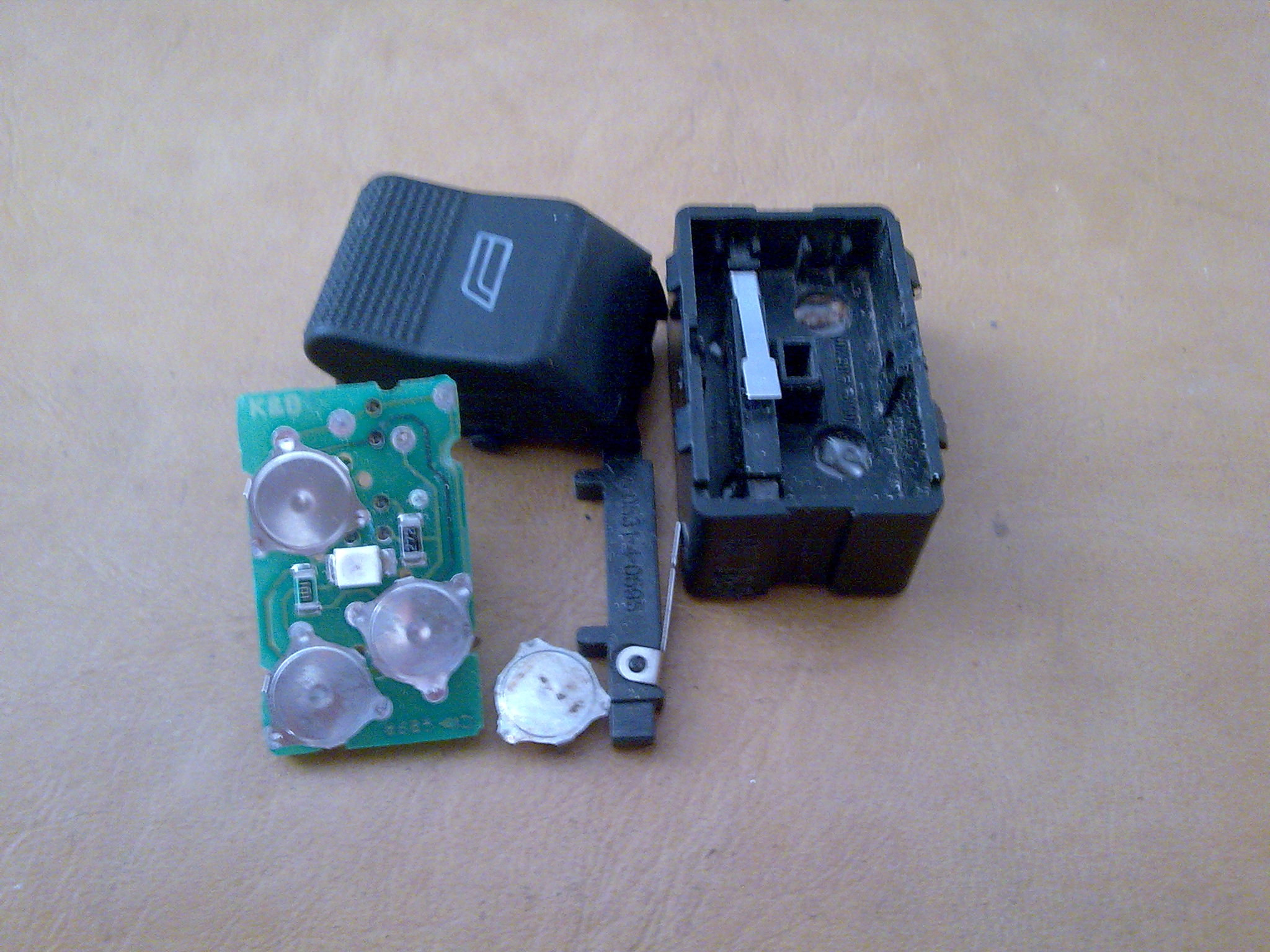
3b. Using the tiny screwdriver, slowly free the black plastic up and away from the switch
3c. The plastic is very fragile and you will break some! But don’t worry too much - as long as the switches snap back in properly, it won’t be an issue. - You should now just see the green PCB and the two sides (i.e., up and down) of the switch. The connections look like copper.
- On mine, on the top of each connection were two obvious build-ups of corrosion - two big dots of silvery-green mess on top of the copper plate. I used the tiny screwdriver to gently scrape this off.
- I also gently scraped away at the two contact points on the underside of the copper contact.
- You can test if it’s working by reattaching and turning on the ignition. If not, stop the ignition, disconnect the switch and keep scraping until it’s all gone/nice and clean again.
- When working, rebuild the switch in the reverse order. The various pieces can only go in one way - it should be fairly clear, although you can get the button the wrong way around!
Driver side
The driver’s side is the same theory as above, except the PCB/switch itself is a little different.
- Disassemble the button as above
- You’ll notice that inside the black plastic housing, there are two small thin strips of plastic with a piece of metal on top. Note their orientation (although they can only go in one way)
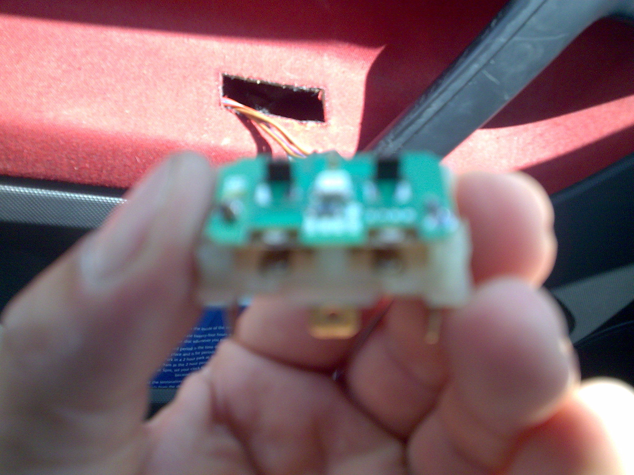
- Withdraw the PCB from the black plastic housing - go carefully and try not to send pieces flying.
- The PCB is noticeably different to the passenger’s side - but the principle is the same. There are 4 small metal “pads” which should came away from the board (i.e., they’re not attached). At the “corners” of these pads are small pads where they make contact with the PCB. The corrosion will be on these pads.
- As before, use the tiny screwdriver to remove the corrosion from the contacts, and also from the pads. It’s harder to test if it’s working because you need the thin black plastic activators.
- Replace the pads on to the PCB - they can only go one way.
- Rebuild the switch as before - the parts can only go one way, except the button itself.
Assuming all goes well, you should now have working switches and saved yourself a nice chunk of change.